EvoClock is a desktop clock that will show the time in words on a matrix of led-lit letters. It is the little sister of the much bigger (and much more expensive) wall clocks of this type. It comes as a DIY electronics experiment kit and can be used to learn the basics of modern open source development architectures like arduino.
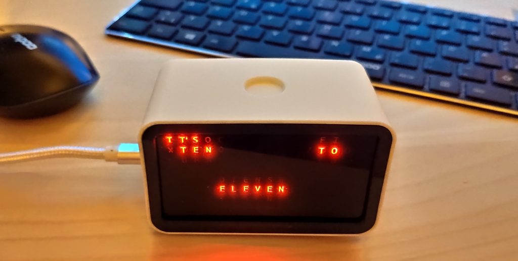
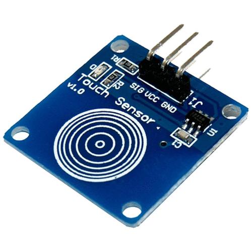
EvoClock has a touch sensor at the top which can react to single-taps, double-taps and tap-and-hold gestures.
Security warning
Please don’t forget: EvoClock is not a professionally developed commercial product – rather an experiment that gives you the possibility to see such a device ‘from inside’. That is why it is delivered as a kit, and not pre-assembled.
Warning! Fire hazard! Choking hazard!
EvoClock is an experimental build-it-yourself kit for demonstration and educational purposes. Loose connections, wrongly connected wires, or design errors might lead to overheating, electric short-circuit and fire. Never operate the device without supervision! When leaving the device unattended, always disconnect it from the power supply! Use an overcurrent protected power source only! This device is not a toy, newer allow children to play with it!
Achtung! Brandgefahr! Verschluckungsgefahr!
EvoClock ist ein Selbstbauprojekt zum experimentieren und lernen. Lockere Steckverbindungen, falsch verbundene Leitungen oder Designfehler könnten zur Überhitzung, einem Kurzschluss oder Feuer führen. Betreiben Sie das Gerät niemals ohne Aufsicht! Wenn Sie das Gerät unbeaufsichtigt lassen, ziehen Sie immer den Netzstecker! Benutzen Sie nur Netzgeräte mit Überstromschutz! Dies ist kein Spielzeug, erlauben Sie niemals Kindern mit dem Gerät zu spielen!
Assembly instructions
Make sure to read the whole instructions first, and then follow it step by step!
To assemble your EvoClock watch the video below as an overfiew and follow the steps described in the text below. A small flat knife, cutter or thin screw-driver might be handy to help push the plastic parts in place, but is not necessarily required.
Take your time – double-check that connections are correct before powering on, and that the cables do not get squeezed in during assembly.
If you get stuck or anything is unclear, or if you find that parts are broken or do not fit, please do not force them in place, but contact us. We can assist you in the assembly process and exchange any broken or mis-dimensioned parts. (Note: especially during 3d printing not all parts might be printed perfectly, and might not fit together in rare cases.)
What is in the package?

Connections
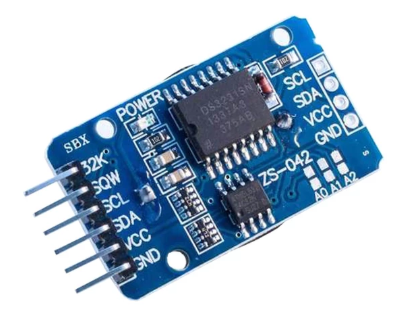
Connect the components as described below and lay them out on the desk. Do not yet put the components in the plastic housing. Pay special attention not to touch any metal parts or surfaces with the soldered joints of the real-time clock module – it has a built-in lithium battery which might be short-circuited – this could lead to overheating, fire and explosion.
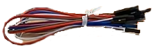
The wires of the display module are already attached to the module, and you only need to connect the “other” end to the Arduino. For the touch sensor module and the real-time clock module, first attach the wires to the modules, then to the Arduino. Watch the labels of the pins on the module and use wires with the appropriate color as detailed below in the schematic and the tables.
If the connectors do not fit tight – but are loose and slip off too easily – please let us know and we will exchange the cables.

Before putting the components into the plastic housing, we will first test the electronics. Before connecting power, double-check all connections, especially the red and brown cables – on both ends. Having them connected in a wrong way might lead to short cuircuit, damaging the components and causing overheating and potentially fire. Also pay attantion which pins you used on the “second row” of connectors on the Arduino – for those there is no explicit labels on the board.
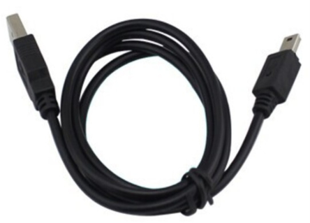
Now test if the electronics work, while they are stilled layed out on your desk. To do this, connect the clock to your computer or USB power source via the USB cable, and check that the display goes on and the time is displayed. Touch the circular metal surface on the touch sensor (the small square board without the battery) to see if it works. The display should react.
Below is a detailed list of connections.
Display module
Connect the red and brown cables of the display module to the pins in the “first line” on the Arduino.
| Device pin | Cable color | Arduino pin |
|---|---|---|
| GND | Brown | GND (on board) |
| VCC | Red | +5V (on board) |
| DIN | Orange | D11 |
| CS | Yellow | D10 |
| CLK | Green | D13 |
Real-Time Clock Module
Connect the wires as listed below, the other terminals remain unconnected.
| Device pin | Cable color | Arduino pin |
|---|---|---|
| GND | Brown | GND (second row) |
| VCC | Red | +5V (second row) |
| SDA | Purple | A4 |
| SCL | Blue | A5 |
Touch sensor module
Connect as detailed below.
| Device pin | Cable color | Arduino pin |
|---|---|---|
| GND | Brown | GND (second row) |
| VCC | Red | +5V (second row) |
| SIG | White | D9 |
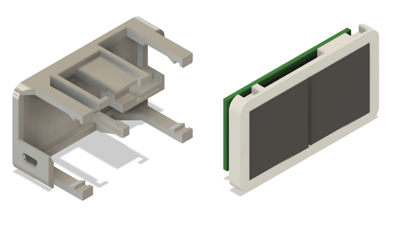
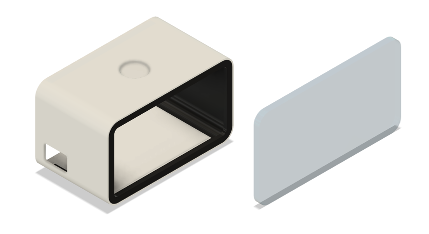
Putting the frame together
Now we will assemble the electronics into the back side of the plastic housing.
Note: The cables are not shown on the graphics below.
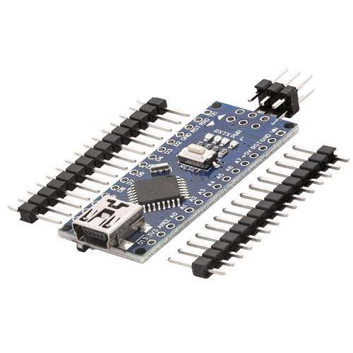
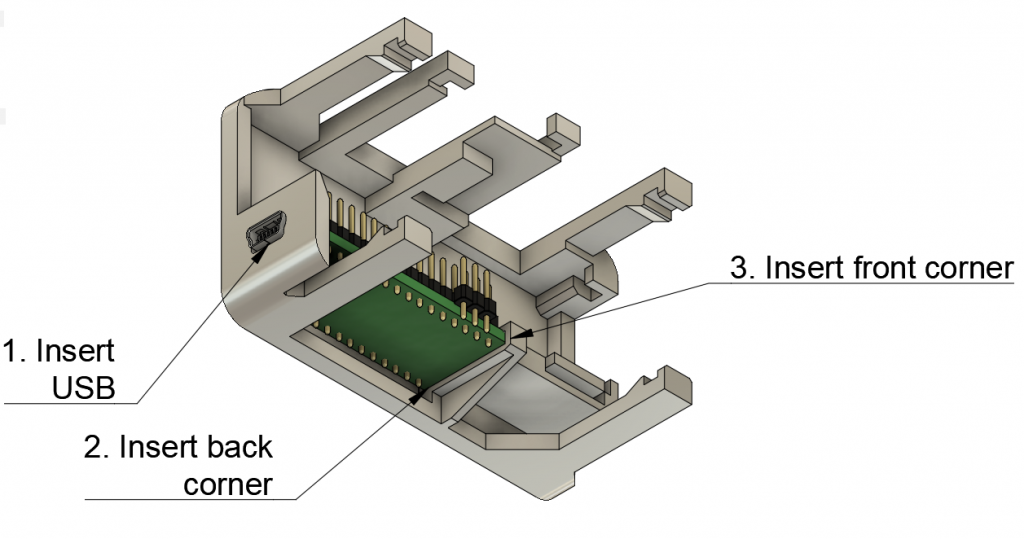
First instert the Arduino into the frame: Put the USB plug and push it gently through the corresponding hole on the left side of the frame. Then insert the right side back corner of the arduino into the appropriate slot, and finally the right side front corner – you migh slightly need to bend the frame to get the Arduino board in place. It should fit tightly.
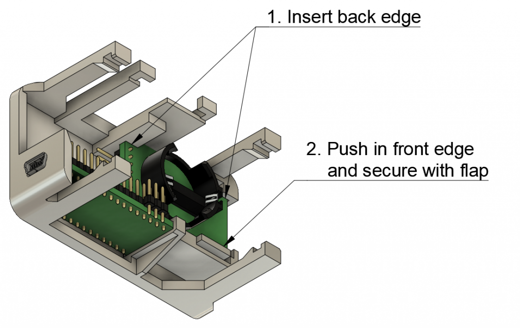
Next arrange the wires as seen in the video. Slide in the Real-Time Clock Module from the right – with the pins facing towards the centre, and the battery facing up. Slide the back edge into the slots on the frame, and finally push down the front edge so that it snaps in place. You might need to pull back the little flap with your fingernail or a knife.
Again, arrange the cables, and put the touch sensor in place.
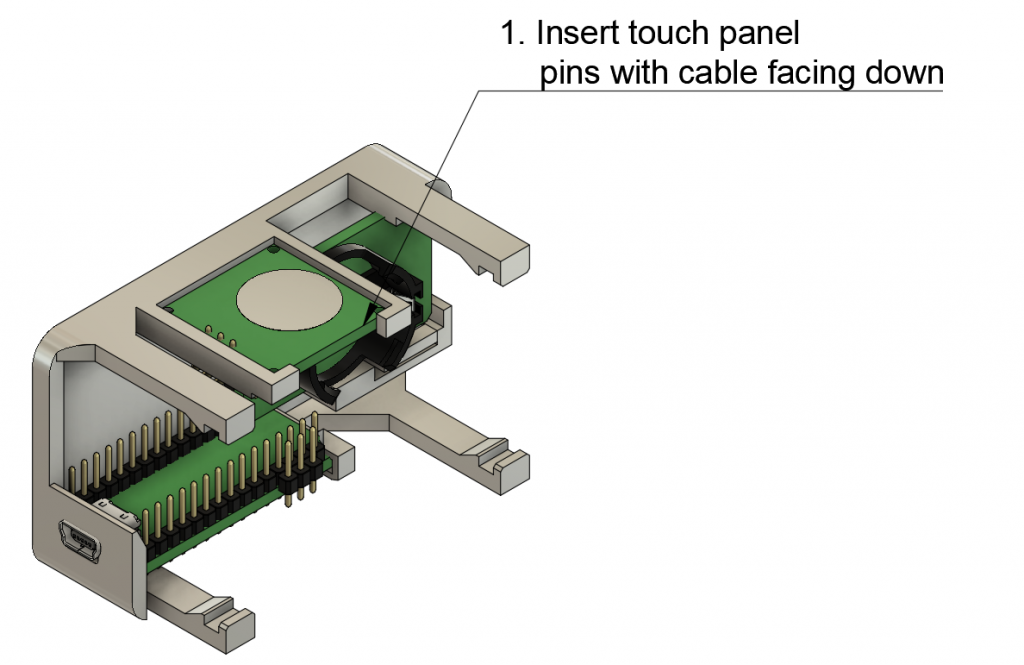
Once again make sure the wires are properly “organized” and will not be in the way when you install the front part of the frame. Arrange the cables of the clock module and the touch sensor at this time, the display cable are not as important at this stage yet. It is best to bend back the cables that hang out on the sides in a U-shape and toss them into the spalce between the arduino and the touch sensr.
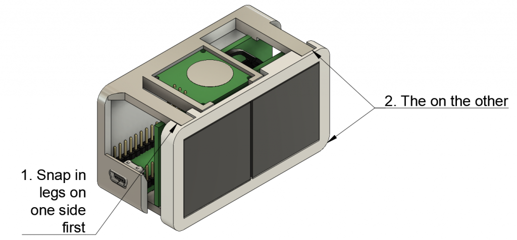
Now install the front frame including the display – mind the proper orientation, it will only fit in one direction (the “legs” are at a different distance on the top and bottom side.) Snap the frame in place by slightly pulling apart the “legs” of the back frame. First the ones on the left, then then ones on the right. Do not use too much force, the legs might break. Also, do not apply any pressure to the center of the display: you might push it out of the frame and damage the black film. Only press the edges of the frame.
Once again, arrange the cables, pushing them into the empty spaces within the frame. The wires of the display have enough space on the right side, while the other cables need to be pushed into the left side of the frame. Be gentle and patient, do not loosen the connections during this step. The best way to slide in the cables is to “push them flat” first, then “reversing them back in.”
Putting on the cover
First of all, stop here for a moment! We first want to test if everything is working fine. At this point it is still easy to correct a wrong or loose connection. Once you put the cover on, it would be very hard to remove it again.
So – before installing the cover – connect the clock via USB and check that it is working correctly. Also test the touch panel, and do set the time (see users manual). Then unconnect the Evoclock from the USB cable, and wait at least 5 minutes. Plug it back in. Does it still show the correct time? (You can check exact time be touching the sensor once.) If so, you can also be sure that the real-time clock module has been connected properly.
Now put the housing on the desk facing front down – the front is the one with the smaller opening and the black frame.
Insert the acrlylic glass and push it tightly – it has to lay flat on the front border. It might be a good idea to clean to the glass with pure alcohol to get rid of any fingerprints. You can also clean the film on the diplay with alcohol.
Slide in the frame assembly into the cover from the back, the display facing down. Make sure that the touch panel and USB port are facing in the right direction. You might need to slightly pull away the back edge of the cover with your fingernails or a knife and/or apply a bit of pressure to push the frame inside the cover. If fully inserted, the little flaps on the back edge of the cover should hold it in place.
Congratulations! You are done…
Assembly video
Users manual
Showing time and date
Touch the circular touch sensitive area at the top of the clock once to display the exact time.
Touch the area twice quickly – like a double-click on your computer mouse – to display the date.
Setting time and date
Touch and hold the touch sensitive area at the top of the clock for a few seconds. After about a second you will see an animated “progress bar” – keep pressing. This is followed by the text “yr:”. Now you can let go – the year set is shown. You can now set the year using the following button presses:
- One quick touch: increase the value by one
- Two quick touches (“double-click”): decrease the value by one
Once you are finished setting the year, touch and hold the button area. Again you will be shown a progress bar, followed by the text “mth:” – you can now set the month the same way. Continue this process to set all the date and time components as listed below. As the last step the text “set!” is shown – after this you are returning to normal operation mode.
- yr: – set the year
- mth: – set the month
- day: – set the day of month
- h: – set the hour of day (in 24 hour format)
- m: – set the minute
- set! – after this screen your are finished setting the time, the clock will return to normal operation
Too easy so far?
If assembly was too boring and you are looking for new challenges, get the source code – and you can modify and customize the behaviour of the clock according to your own taste – let’s say with a personal greeting. Alternatively you can also start from scratch and try to re-program the logic.
To start developing:
- Get the Arduino integrated development environment from: https://www.arduino.cc/en/Main/Software – download the windows installer version and install it
- Once you started the Arduino IDE, got to Tools -> Board -> Boards Manager and download the version 1.6.20 of the “Arduino AVR Boards by Arduino” packaged. Even if a newer versionis already installed, please downgrade to 1.6.20 as with newer versions we faced problems problems uploading the program to the board.
- Plug in the EvoClock and install the USB Serial driver. The chip on the board is a CH340 type one, so you will need the driver “USB-SERIAL CH340” (Manufacturer: wch.cn)
Note: installing drivers from untrusted sources might pose a security risk! - Download the source code below. All files need to be in a single folder with the name EvoClock. Open EvoClock.ino – Arduino IDE will also load the other files. The source code split to separate files to make it easier to overview.
- Make sure to configure the language in the main include by uncommenting exactly one of the lines
#define LANGUAGE_DE
or
#define LANGUAGE_EN - To compile and upload to the board first select Tools -> Board -> Arduino Nano and Tools -> Port -> COMx. Depending on which USB port of your computer you have connected the clock there is a different number in place of x. If you do not see any COM ports listed, there is a problem with your driver installation.
- Press the upload button in the toolbar – the second one with an arrow pointing to the right.
To get the source code please get in touch with your favourite Evosight employee 🙂